
The end is in sight!
Like the title of this post says, the end is in sight! During the course of this build (which has taken over a year), it seemed as though I would never get the boat complete enough to test in the water (one has to almost fully build the boat prior to even doing a proof of concept test). I set a deadline for myself to complete the build end of february and launch sometime in march, and I think I might actually make good on that self-imposed deadline. So here is a little update of whats been going on with LoCARB since the last sad update.
Quick topics in this post:
- Motor Pod sawed open and battery replaced
- Nose cones made
- Rudder Bent, so modify!
- Tests in the Lake – Fail x2
- Autopilot configuration and counterfeit GPS units
- Solar Panel mounted
Motor pod cut open and battery replaced
In my last update shared how during testing (after I sealed up the motor/battery pod), that the battery was bad. It did not hold a charge and went dead after 2 hours. I seriously contemplated just finishing LoCARB and sending it on its way with the bad battery and letting it move during the day and literally sleep during the night. However, I just couldn’t let LoCARB hobble along and not give it its best shot at reaching Hawaii so I cracked open the pod (literally) and replaced the battery.

The bad battery. Bad battery!
I first tried hack-sawing the place where the end-caps met the duct, and whacked it many times with a rubber mallet. I was hoping the PVC cement would crack and let loose allowing me access to the interior of the pod. Alas, that was not to be (in fact, I realized how durable the housing actually was during this time). Much pounding and sweating later, I just opted to cut one side open with a hacksaw which would give me some access to put a pole through the ducting to place against the other end cap and hopefully with a few good whacks with a hammer, pop the front cap off. This idea worked to some degree as it did pop the front end cap out, but it also cracked and broke off several pieces of the ducting itself. There went my hope for the ducting-to-end-cap waterproof seal.

Front end-cap popped out OK.

Had to saw out the rear end-cap. You can see the duct remaining on the face of the cap.
Replacing the battery was uneventful as I just needed to do an exchange (although I had to drive across the bay), but they gave me a $10 refund with the exchange.

Here I am cementing the broken off pieces back onto the tube.

You can see a little of the outline of the piece that broke off here.

Back to square one.

You can see where I initially tried to cut along the cemented faces. Ugly…
While I had access to the motor pod again, I went over the fittings again with some 3m 5200 to better seal them, and also removed the solar charge controller Bluetooth dongle. Ill use that for future projects.
I needed to 3D print some retaining brackets to line the inside of the duct so when I pressed the end-caps back on, they would not slide too much off center while slick with PVC cement. They worked quite well, and provided a bit of support. After the battery was replaced and end-caps cemented on, it was time to make the nose cones.
Nose cones out of half dome foam
Making the nose cones were pretty straight-forward. Buy some half circle craft foam, then shape it to the desired shape using a razor and sand paper. They aren’t perfect, but they’ll work.

The most difficult part of this process was drawing the reference lines center to help with the shaping process.

Incomplete rear cone.

I needed to make the cones before I began to fiberglass as I wanted to interweave the fiberglass layers of the nose cones to the fiber-glass layers used to re-seal the motor pod for added strength.


Here is a close-up shot of the fiber-glassing process. I used tape just barely touching the front edge of the end-cap and around the edge of the nose cone to keep the epoxy from escaping and leaving air voids in the fiber material.

Done fiber-glassing cones (notice no rudder skeg)

After epoxy cured and sanded smooth (notice rudder skeg)
Rudder Bent, so modify!
While sanding the nose cones I walked backwards into the rudder with only a little force, and my rudder shaft bent to the point where the rudder would no longer rotate freely. I bent it back but realized that I needed to stabilize it since it really didn’t take that much pressure to render it inoperable. At this point in the process, I was a little tired of fixing things so I just decided to make something that would work without too much hassle.
Enter the 2 for $8 aluminum carpenter square.

To build it, I cut off the thick front edge of the square and designed and printed a centering support which would level the square with the rudder. The support was necessary as the shape of the hull would require it to be supported when I fastened the apparatus with 6″ bolts. Before I affixed the rudder skeg support contraption, I added 5 more layers of fiberglass to help strengthen the hull where it would be attached. The bolts were then screwed through the fiberglass skin of the hull, up into the foam, and finally into the 2×4 backbone.
I then cut a recession into the rudder fin and printed out a support arm which was attached to the rudder skeg support using nuts and bolts (the arm holds the rudder shaft), sealed it with some marine sealant, and it was good to go. The aluminum skeg is rigid but somewhat brittle, as I tested the second carpenter square that came in the package. If the skeg is hit with enough force, it should break free rather than bend, which I hope allows the rudder to keep moving…albeit with something hanging off of it.

Tests in the Lake, Fail!
Day 1:

Once all the fiberglass cured, the boat was ready for its first real tests in the water. I was hoping to test out the navigation and just observe its general performance. One thing I was unsure about was whether or not the boat would be too floaty or too heavy as when I did my calculations, the motor pod was effectively neutrally buoyant but with all the fiberglass and random parts added I was a little unsure which way it would go. Turns out that with the addition of the nose cone foam, it was too buoyant, and the boat would capsize if left sitting in the water. I tried to poke some holes and let the water in, but the foam was displacing too much water.

Making some holes for water ingress into the cones.

Here I am with my little boat.

Connecting to the autopilot.
Since I didn’t have anything to weigh down the motor pod, I accepted defeat and went home to fix the foam issue for the next day of testing. While at home, I poured a bunch of acetone inside the nose cones through the holes I made earlier and dissolved a large percentage of the white EPS foam.
Day 2:
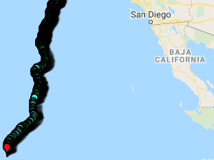
This day yielded much better results. After some experimentation, it only took about 8lbs of additional weight to keep the boat from capsizing and run stable (I still had a bunch of pink XPS foam remaining in the rear cone so that is next to go). I was also able to do a few guided mode waypoint runs using the autopilot and test out the manual performance using an rc transmitter. Its a slow moving and slow turning boat, but it does do both!
Time to tackle the autopilot issues…
One thing I ran into was the autopilot was not tracking competently as it would zig zag to and from waypoints if it headed to a waypoint at all..
After bringing the boat back home, I began to tackle the autopilot issues and found several things which was causing the trouble.
- My autopilot compass calibrations were way off causing the navigation to not enter auto mode
- The GPS/compass is counterfeit. Which would also not allow the autopilot from entering the autonomous navigation mode.
My first step in the process was to start from the beginning. I upgraded my autopilots firmware, reset the configuration to default and began the initial setup of compass and accelerometer calibrations. However, despite doing this, the autopilot would take forever to gain a gps lock, and even if it did would not allow the EKF or extended kalman filter to normalize (which is a requirement for entering fully autonomous mode). I looked into the gps included with my ebay pixhawk flight controller and found it was very likely a counterfeit unit.

These counterfeit ublox m8n units are generally of poor quality and performance.
I hit amazon and ordered a Mateksys M8Q-5883 GPS and compass combo and found that its performance far surpassed the one I was using previously. The amount of satellites it would lock onto were far greater, and the lock was achieved much quicker than the counterfeit unit. Its also much smaller!
Using this GPS, the Pixhawk 1 flight controller calibrated true, and although the EKF would still take a little time to normalize, would actually do so!
Because of this process I realized that the autopilot however, would not automatically enter the auto mode on startup which would render my boat useless if it ever restarted in the middle of the ocean as it would just sit there waiting for RC input. No matter the settings I tried, it would not enter the auto mode. Some forum members mentioned there are a few bugs with the latest version of the firmware and I would have to wait for them to be ironed out for the capability to function.
Instead of waiting however, I implemented a workaround and wrote a quick mavlink function for the Arduino companion computer to continue to try setting this mode until it was able to, and once confirmed successful (only if the GPS fix and EKF normalized), would then start the motor. It works a treat for making sure the autopilot is in the autonomous mode before starting its journey (I admit I had to relearn all my previous programming and it was a bit stressful).
Mounting the solar panel
Besides final sanding and painting, one of the last steps of the process is permanently mounting the solar panel.
I cut and drilled aluminum angle and flat stock and ordered aluminum nuts and bolts. I also printed some grommets/spacers to be used for the assembly where metal touches metal. I also shortened the solar panel wires and installed/crimped new MC4 connectors so there was less loose wire flopping around. The connectors also seem to be of higher quality and offer better waterproofing than the ones included with the panel.

I needed to create a waterproof connection for the MC4 connector leads, so came up with this idea using PVC pipe.

Assembled and sealed. The wires go through two drilled holes in a PVC end-cap

Platform modified to fit and 5200 glued/screwed/bolted to the top of LoCARB

A shot of the grommets acting as spacers where metal meets metal (not shown, brass rings on solar panel insulated from touching the aluminum bolt and angle.

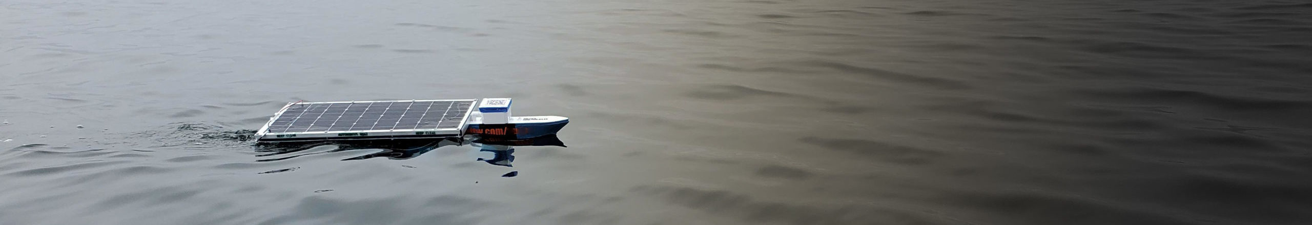
Finished dry fitment of the solar panel. Just needs some 5200 on the nuts.

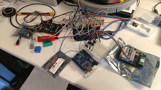
LoCARB waiting for sanding, paint, and identifying decals. Electronics box open because always working on it.
LoCARB is almost finished. If it can successfully complete a few autonomous mission plans in an efficient manner (im sure ill need to tune PID values) the next time it goes to the lake, it should be ready for the ocean. Next testing on the lake will need to wait though as i’m waiting for two different propellers coming in the mail.