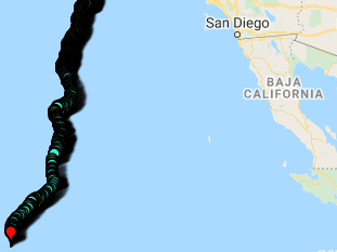

LoCARB gets a new power supply for the refresh
When I set out to build LoCARB for the first time, I tried to avoid building a lithium battery pack because of its additional complexity and price. Since then, I’ve gained a bit more confidence in my electronics skills and also discovered lithium battery cells have come down substantially in price since! Because of this, it was time for LoCARB to get a newly designed power supply in the form of a 40 cell 18650 4S10P battery pack with BMS to be used in conjunction with a Victron 75/10 MPPT solar charge controller, woo hoo!
Want to learn more about building an 18650 battery pack? Head here.
Which 18650 Cells?
Evaluating the power and cost requirements for LoCARB led me to find Samsung 30Q 18650 cells from imrbatteries.com. These cells are rated for 3000mAh with a max continuous current of 15A (well below my intended 1.8-2.1a max running consumption). At $3.99 each + shipping costs, the total came out to be $166.52 (I even got a nice wire snipper for free, score!). This is less than the price I paid for the 105Ah car battery.
One consideration is that the operating voltage range for these cells is 2.5v to 4.2v (but shouldn’t be brought lower than 2.8v). This equates to quite a voltage swing during the duty cycle of the battery pack. Because of this, I needed to design my battery pack to provide greater than 9-10ish volts (I’ve found my motor doesn’t really spin at less than that) so my capacity and voltage requirements dictated at least a battery pack designed with at least 4 cells in series (which gives me a voltage of 11.2v – 16.8v). Afterwards, it was just a matter of figuring out how many mAh I needed in parallel to cover my power requirements for a full day.

Battery Configuration
Since I’m planning to launch in May, I should be getting about 9 hours of sunlight with about 15 hours where I wont be charging. Also, given that I’m looking to run LoCARB with a consumption of about 15-21 watts of power per hour, I would need ~315 watt hours capacity to cover the 15 hours LoCARB is not charging.
An 18650 lithium battery wired in 4S is 16.8v and with 10 30Q 3000mAh cells in parallel, that gives 28 amp hours (if using this data for real world mah specs) of capacity. This equates to 470 watt hours @16.8v of power with a nominal capacity of 403 Watt hours of power at 3.6v. Since lithium battery packs can be discharged at 80% capacity, this gives me a total of 322 Watt hours of power to use. This leaves me with 7 Watt hours of capacity left over (which it just enough to cover my energy needs). Granted, this is in the best case scenario, but whatever. Ill stick with this configuration and fine tune the throttle to cover any undesirable excess power consumption if I want to have a little more cushion etc.
**NOTE: whatever goes out, must come back in…Remember that with the amount of capacity one expends, one must replenish with solar energy. One must size the panel(s) accordingly to charge the battery back to capacity within a reasonable amount of time!
Building the battery pack
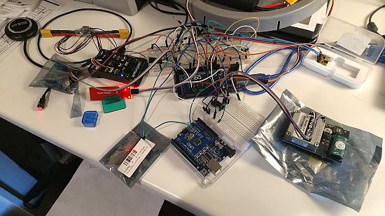
Much to my apprehension, the cells have some assembly required which unfortunately requires building another electronics doodad, a battery spot welder (cue violins). Although I won’t detail how to go about building it in this post, all it requires is a car battery, some 4/8 gauge car jumper cables, copper spot welding tips (I used a short length of 12/2 Romex laying around and stripped the insulation off), and a motorcycle starter relay (some people don’t even use a relay…but that seems crazy to me). I will however, post the code I wrote for the Arduino Uno I used to control the relay (with another relay) to get consistent welds in the code and guides section.
A note about the nickel strips… since I’m pulling 2-3 amps max out of this battery, any thickness nickel strip should suffice, but for posterity I just purchased and welded lengths of a .15mm pure Nickel strip from eBay.

Battery spot welding station. Arduino for welding control hooked up to a 5v USB car adapter which is hooked up to a 12v cigarette plug. Car battery is a 12v SLA 550 CCA battery. Negative welding lead hooked up to the motorcycle starter relay which is controlled by the Arduino.
The 4S10P battery pack should ideally look like this depending on your desired + and – orientation :

Welds on one end

Welds on the other end

After measuring the available space within the 4″ ABS pipe, I realized I needed to keep the cells as close together as possible. This ruled out using spacers of any kind, so I just hot glued 10 cells together at a time, then glued the 4 lengths of 10 cells together to make the cell block. Prior to building the battery pack, be sure to fully charge and balance each individual cell to the same voltage!

Afterwards, I spot welded them into place. I found that its best to test the spot welds on individual throwaway cells (if you have any) to dial in the spot welder delay so as not to burn through the cell and have it burst at the negative end (how would I know this? ha ha…sigh). Also, its safer to start at the + side when using a freshly charged car battery as it is a raised metal surface. This allows the voltage of a fully charged car battery to come down a little so as not to expose the negative ends to excessive voltage when welding.

Another side

Cheap AMBEST Enhanced 4S 16.8v 40a BMS from Amazon. Works fine.

BMS wiring diagram

The BMS allows for charging and discharging using the same wire leads, and also provides protection when it detects over-current and over-voltage discharge. I don’t ever want the protection to disconnect my Arduino or motor, so I soldered two additional XT connectors in place to bypass the BMS and supply direct power to those leads instead.

Charging through BMS works and the MOSFETs run cool.

I set the charge voltages to 16.81v in the Victron 75/10 MPPT solar charge controller to limit the charge voltage sent to the BMS. Since the boat should be running at almost always less than 16.8v, it should be ok for battery pack.
**01/16/2021 I’ve since tested that the BMS will kick in its voltage protection at ~16.7v. Any excess voltage will be converted to heat and the fusible resistors (I think that’s what they are) will heat up to around 120 degrees F. Best to keep charging voltage to 16.70v or ill be fighting the BMS.
Calculating maximum charge rate:
Each 30q cell has a maximum charge rate of 1.33. This equates to 4 amps per cell. Since I have 10 3000mAh cells in parallel, that equates to 30 amps x 1.33 = 39.9 maximum amps charge current per cells in series (I have 4). Because my solar panel cannot output more than 6 amps, Ill just set it to 6 amps max charge current.
Power supply completed, lets try it out!
With the power supply completed, it was time to find out how the new ESCs I purchased worked with the new power supply voltages. Unfortunately, the results from the two ESCs I had purchased were terrible and they burned up or triggered the internal thermal protection which gave erratic motor operation. Not good. Fortunately, Slava from the Brave Puffin project suggested a FlyColor ESC which worked out beautifully. It was also a direct drop in replacement for the initial startup calibration routine which I had already programmed into LoCARB. It ran cool and operated very precisely.

A horizontal test container which can break up the water flow (compared to a circular one like a bucket) is ideal as it does not allow the water to swirl and spin with the prop which provides inaccurate results.

A cheap ESC burning out.
Dialing in the new power supply and magnetic coupling
Because the new power supply operated from 11.2v to 16.8v, I needed to adjust the PWM settings according to the performance I desired from the new motor/magnetic coupling. What I found was that the optimal operating RPM for the targeted power consumption was still the same as the previous generation magnetic coupling, 1000-1200 RPM. Pretty Cool!
Here is what I found on a fully charged battery:
| PWM | RPM | POWER | VOLTAGE | TOTAL AMPS CONSUMED |
| 1400 | 1330-1360 | 28W-33W | 16.14v | 2.13a |
| 1370 | 1210-1300 | 26W-28W | 16.18v | 1.70a |
| 1330 | 1140-1170 | 19W-21W | 16.28v | 1.19a |
| 1300 | 1060-1090 | 16W-17W | 16.31v | .98a |
Testing seemed to show that 1300-1330 PWM will be the MINIMUM PWM ill need to specify to achieve the RPM/power consumption target. If the battery voltage drops lower as it continues to run throughout the day, I will need to bump up the PWM to achieve the target 1000-1170 RPM. Knowing that the voltage directly affects RPM on these RC motors, ill need to rewrite my N.U.T.S. code to keep the target RPM throughout the voltage range.
TO DO:
- Full 24hour test of the propulsion and power system
- Implement autopilot hardware fix
- Assemble and fiberglass the pod to the rest of LoCARB