
Consolidating with a mini mega and soldered protoboard circuits
Consolidation, durability, and connection
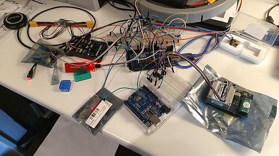
While waiting for my solar panel to arrive from China, i’ve been soldering the individual electronics onto protoboard and organizing the layout to what I believe is the most efficient way. I’ve created two dedicated circuit boards, both mainly to distribute power and to connect the leads/wires in a durable manner. One circuit board will live in the motor/battery pod and connect a DHT22, DS18B20, Leak sensor, RPM sensor, and the ESC controller. Signal wires will run up one motor pod strut and connect directly to the mini Arduino board (except the DS18B20 as that connects to the other circuit board so I can run it in a one-wire configuration), and power wires will run within the other pod strut. The other circuit board will live in the electronics box with the Arduino, Pixhawk, Rockblock satellite modem, and relay. This board will connect a 2 channel relay, DHT22, DS18B20, Arduino watchdog, and tilt sensor. The signal wires for the listed sensors will directly connect to the Arduino board.

In an attempt to cut out unnecessary bulk and components, I found a miniaturized Arduino without the USB to serial converter chip on Ebay (it can come with pins soldered or unsoldered). I chose the unsoldered version as I would solder the wires directly to the Arduino, which turned out to be slightly more cumbersome than I anticipated due to the small size of the board (it measures 2.12″ long by 1.5″ wide).

After some initial testing, I found that it seems to be slightly more susceptible to voltage fluctuations compared to the other Arduino Mega 2560 that I was using for breadboard testing, so i’ll need to put it through its paces to ensure reliability.

One side effect I encountered when using longer wire leads to interconnect between the circuit boards and the Arduino was that it introduced a value of 170 RPMs when just the long wires were connected (even if the sensor was disconnected). This was causing my motor monitoring function not to work correctly as I programmed it to detect a RPM of 0 before it initialized the motors (I am actually thankful for finding this now rather than later). I just set the value to be ‘<= 300’ threshold instead. I also offset the formula for determining RPM by 170 to account for the bias.

I need to finalize a few things such as wire up the relay circuits to be able to power cycle the Pixhawk and ESC, and I also need to calibrate the Pixhawk power module with my AGM battery for voltage and current sensing. I hear that the power module isn’t very sensitive for detecting current readings under 3amps, so Ill need to see if this is a value I want to transmit after all. I do need to wire in a switching voltage regulator for the rudder servo, as well as for the Arduino, then I think I will pretty much be finished on the electronics part of the build. Oh I have to connect the camera as well, but that can come a little later.
Here’s a sketch just for the heck of it:

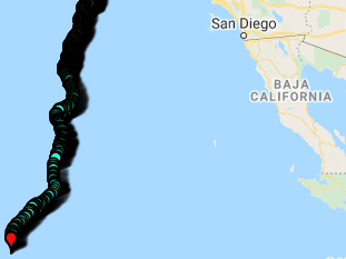
Thinking through what to do if LoCARB is found…
I have been thinking about what to do if LoCARB is ever found, whether at sea or beached on a coast somewhere. In the likely event that LoCARB is ever found, I hope that establishing bi-directional communication will provide the best way to get LoCARB back in the ocean or back to me. I’ve since created a landing page which will be written on the side of the hull where anyone who happens to come across LoCARB will be curious enough to visit. The page describes what the LoCARB project is, provides operational condition of LoCARB, instructions on what to do relevant to its status, and contact information (I will update the landing page depending on status). The page is incredibly concise (K.I.S.S.) and will hopefully guide the discoverer into establishing communication with me.