

LoCARB refresh
Building an autonomous boat from scratch is strange. It takes a lot of time, effort, and energy, and it sort of becomes a part of you in ways you cant really understand. After I brought LoCARB home from its failed second launch, I was convinced I was finished with the project, as I just didn’t want to hassle with the boat anymore. But after a few days some things began to nag at me. Did the rudder still work? Were the electronics still usable and in good condition? What other damage was done to the functionality?
Triage
After some probing and re-jiggery, I found that despite the missing pod and frayed wiring, the electronics and rudder were fully operational. The only thing that was missing was well, the power supply and propulsion systems. If those were replaced, the boat could potentially sail again.

Body cut down to gain access to what remained of the struts
Work Begins
Body and Wiring
With nothing to lose I cut down past the broken struts and was able to expose the severed wires with enough usable length to attach new wires. Because I was working with PVC pipe, I was able to slip a coupling onto the end and attach a new section of pipe to create new struts.

I had to break off epoxy which encapsulated the wires, which was a lot more difficult that I thought. Good thing it cracked with enough pressure.

After exposing enough usable wire, I was able to solder another length of wire to the end.
After the wires were connected, I heat shrank them and dropped a 1/4″ piece of rebar into each strut. I found that carbon fiber is too weak after it cracks to be much use as a structural member in these struts.

Extra lengths of wire attached and ready to go

I once again filled the struts with epoxy and reattached the removed body sections.

Body sections installed and ready for fiberglass
Motor Pod
With the body portion pretty much repaired, I then needed to work on the motor pod. One thing I was certain of was that I wasn’t going to try and build it using another car battery as it was just too bulky and cumbersome to move around. I also found that by using 18650 batteries, I would be able to build a battery pack for roughly the same price as a car battery.
From 11″ duct to 4″ pipe
The switch to using a higher density power storage system allowed me to use a 4″ ABS pipe instead of a 11″ PVC duct, which really helped in the design of all the other components.
Magnetic Coupling
Because I moved to a smaller pipe diameter, I was able to use my 3d printer to build the magnetic coupling for 80% of the components. Armed with more experience and learning from my first design, I incorporated a few improvements which I hope will make the coupling more robust.
Improvements in design:
- Stronger magnets to allow for larger air gap tolerances in order to use a thicker 3d printed waterproof barrier
- Rotating prop shaft assembly rides on ball bearings
- No rubber seals of any kind
- Magnets are not held in place by epoxy but by the printed assembly hopefully reducing possibility of a failure.
- Prop shaft supports the point where the magnet carrier rides within the ball bearing.
Stronger magnets
One of the major limitations of my original magnetic coupling was the maximum air gap from motor side magnet to propeller side magnet. This limited the thickness of waterproof barrier, and was a huge weak point in the design. It required a machined plastic part instead of a 3d printed part due to the weakness of a thinly printed design.

I also learned that the length of the magnet has a greater “holding” effect compared to the depth of the magnet. Therefore, I tripled the length of the magnets in order to achieve greater holding power.
One of the drawbacks to using larger magnets is the additional weight the magnets impose on the design. As such, any imperfection in any of the parts will cause more vibration to occur due to the imbalance of the rotating assemblies. I was worried about this so I designed the inner magnetic coupling portion to incorporate the propeller shaft into the nub that rides within the bearing.

The nub can be seen more clearly here. It is hollow and allows the propeller shaft to be inserted within the cavity.

Shaft and flange coupling installed. The flange coupling is screwed into the black magnetic housing and has set screws to keep the shaft from rotating.

The front portion showing ceramic bearing installed.

Magnetic coupling components

One thing I noticed during the first two launches was the interior of the motor enclosure was running at about 117 to 125 degrees F. This probably meant that the motor was probably running around 135 to 150 F or even more (just guessing). This reinforced my need to use ABS for the motor side coupling as it has a higher glass transition temperature rating than PETG, and I also designed a recession for the little metal round thing that comes with the motor so it can sandwich the ABS with the screws holding it in place. Once the assembly was screwed into place, I also filled the flat portion with epoxy to provide more rigidity in the event the ABS did hit softening temps.

Epoxy applied to the Motor side coupling and metal round disc thing visible.

How the assembly comes together. White part is the waterproof barrier with walls 3mm thick.

Motor-side coupling on 3D printed PVC pipe end cap. Each concentric ring will be filled with epoxy to further strengthen the end cap.

A PVC coupling (white bottom part) serves as the main body for which other 3d printed parts are attached. Also shown is the end cap.

Interior of the propeller side housing which slides over the white PVC body. This is the cap which supports the waterproof barrier and connects the body to the propeller-side assembly. The fingers are to center the waterproof barrier and give additional protrusions to which the epoxy can adhere.

3D printed carrier for rear bearing to be installed at end of the 3/4″ pvc pipe exiting out the rear of the assembly

The waterproof barrier installed and epoxied in place

Rear cone and end cap installed
First Test of the assembled coupling.
To be completed…
- Battery Pack
- Solve the Pixhawk navigation problem
Battery Pack
I have a few months before the next launch. In that time I hope to have a fully tested battery pack, and a fully assembled/fiberglassed motor pod. Currently, I have all the 18650 cells but haven’t pulled the trigger on a BMS solution just yet. I may just purchase several BMS circuit boards and test to see which ones work the best.
Solve the Pixhawk navigation problem
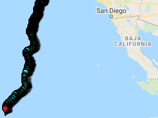
On the ill fated second launch of LoCARB, the navigation system went bonkers. It got stuck in a hold mode, and also suffered a few reboots from the watchdog rebooting the unit due to a hang. This could happen with the failure of certain pre-flight checks (which I disabled completely) or something that I haven’t accounted for like the compass not being good at tilt compensation, or a compass working incorrectly…or the calibrations being done incorrectly (or…or…haha).
Upon more research, I’ve narrowed it down to a bad initial boot calibration (starting the boat on a rocking boat will throw off the accelerometer and IMU calibrations) AND possibly a bad IMU hardware bug that is present on clone Pixhawk units.
As such I have implemented the following software fixes:
- INS_GYR_CAL to 0 to disable startup gyro calibration
- FS_EKF_THRESH to 0 (disabled)
And the following hardware fix:
As referenced here: https://discuss.ardupilot.org/t/second-imu-error-when-arming-pixhawk-2-4-8-copter-4-0-1/51554/4 and https://diydrones.com/forum/topics/solution-proposal-for-pixhawk-imu2-related-bad-accell-health?id=705844:Topic:2124935&page=1

The fixes shown above should remedy the issue, but I cannot be certain of this until I actually get the boat out into the water for testing. Will report back later. That’s all for now.

One thought on “LoCARB refresh”