
What the hull…building the boat and stuff
It has taken over a year to build LoCARB…and I gave myself till end of January to get it completed… The only thing that’s left now is to mount the solar panel and come up with an appropriate way to connect the panel wires to the solar charge controller. Oh wait, yeah I need to make fairings for the struts and cones for the front and rear motor pod ends (sigh). I’ve since sealed the motor pod containing the battery, motor electronics, and sensors, and assembled the top cover to the rest of the body to complete the hull. I’m actually pleasantly surprised at its flexibility and rigidity, and hope it will be robust enough to survive spending an extended amount of time in the elements. This is the first time I have ever worked with fiberglass, but I found it to be quite a remarkable method of creating strong and durable skins for any purpose. I hope to use what I learned in future projects…Anyways, on to the pictures.
The Hull

To get templates for the hull, I created a lines plan with Delftship…I didn’t have access to a plotter, so I just traced the cross sections to scale 🙂

Taping the templates to cardboard and cutting it out.


Spacing out the templates to visualize the hull

Cutting the XPS foam board to appropriate size

Only use 3m spray adhesive to glue the pieces together. I tried to use wood glue, and it ended up dissolving the foam!


Doesn’t really matter if its not uniform for this part. It gets trimmed away anyway.

This is the foam cutter my neighbor let me borrow. A good way to make straight vertical cuts is to just turn the sucker on and let gravity do its work.

Making vertical cuts…

Each section cut using cardboard templates on each end as a guide.

Rough shapes cut and aligned!


Looks terrible…

After sanding a bunch. A little better…

Nose is a little big…


Sanded down nose to make it a bit more streamlined.

Here is the center cavity which will allow the 2×4 wood backbone insert to be used as a “hard-point” for mounting.

2×4 cut to fit. Holes were made to reduce weight.

Checking out how everything fits together. You can see the beginnings of the motor assembly on the bottom right (white PVC toilet flange).


Dry run of the wires to determine length and assembly order.

Is this what its going to look like?

Screws installed for solar panel mount points. Holes drilled for struts.

Some random bits of stainless steel tubing to be used to keep threads from cutting into wires which run through PVC pipe.


Dry fit with rudder servo waterproof box

Before fiberglass


Fiberglass applied

Cut the top cover for the hull and drilled appropriate holes for the protrusions.

Wires run and prepping for final assembly of PVC pipe. I went with 1/2″ PVC pipe.

Epoxy poured into struts with 1/4″ carbon fiber shaft insert for rigidity. As a test run I poured epoxy into a 1/2″ PVC tube and let it harden. I then jumped on it several times and noted how incredibly strong and flexible it was. I figured it should be a little more rigid, but still flexible enough to not crack so I added a 1/4″ carbon fiber shaft down the length of the struts. I have a feeling I should have just stuck with epoxy, but we will see.
On first try, I plugged the holes at the bottom with tissue paper to keep the epoxy from escaping. That proved a very bad idea and let the epoxy flow out…it created a huge mess. I realized that a little hot glue works great!

Epoxy and carbon fiber rod.
Rudder Assembly

Rudder tube is just plain 5/8″ brass tube with 4 Rulon bearing inserts and two cup seals (2 bushings per cup seal).


3D printed rudder tube support. I also got an aluminum servo arm and drilled a hole partway through the rudder shaft to prohibit slippage. Shaft is 316 stainless steel. Metal epoxy applied and set screw installed.

View of how assembly will look without hull.

Rudder electronics box is just an electrical box.

Rudder fin is 3d printed out of ABS and rudder shaft is drilled to accept some pins to keep shaft from free spinning. Two halves solvent welded together then fiber-glassed with 3 layers of fiberglass. Its apparently good to have the shaft in the first 1/3″ of the rudder to maximize torque and reduce power consumption. Its also efficient to have a maximum rudder rotation of 30 degrees, says the internet.

Before sanding and fiberglass

3D printed servo mount adhered and physically attached to box. Can’t have it dislodged and free floating…

Finished servo assembly. Rubber boot attached with 3D printed attachment. Sealed 3D printed part with a bunch of solvent (not shown).

Close-up of rudder compartment and wood support for rudder tube

Test fit.
Servo and rudder arm dry fit.

Testing everything before assembly…

Cavity filled with foam. I didn’t show it but the rudder electronics box was sealed with a flexible marine sealant and not the foam gasket that came with the box.
Meanwhile…
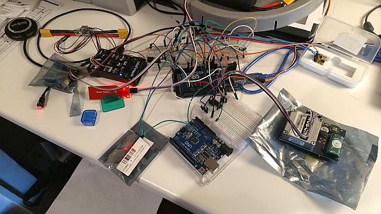
When all that was being done, I also tested the solar power supply, satellite communications, and reliability of the electronics for a week. Everything worked nonstop without any problems!

The bucket contraption is the motor and prop spinning the bottom bucket filled with water. Not 100% accurate, but I needed a convenient way to apply load to the motor.


Testing to see if my calculations were correct with the motor pod being neutrally buoyant…It is!

While working outside, my kids decided to join me. “Don’t spray the Tupperware box!!!” was repeated many times that day.
Motor Pod
The motor pod is just a 10″ thin-wall PVC duct. I figured that it would be easy to work with, reasonably strong, and allow for a watertight seal using PVC cement. The only issue was how to mount the 70lb AGM battery inside and keep it from rolling around. I came up with this confounded support system.

I 3D printed some rounded feet which allowed tubing to be inserted which would allow two additional feet (modified to accept 1″ nylon straps) to slide along the tubes for adjust-ability. The two sliding supports would hold the battery to the assembly which would be cemented to the tube.

After the support structure was cemented to the duct (when drying, I put the battery on top of the feet to help adhesion). The yellow straps are 1″ nylon with cam buckles to allow for tightening the battery to the support.

Solar charger mounted with good ol’ duct tape. If its good enough to go to the moon, its good enough for me! I swapped out the 20amp fuse on the solar charger with an auto-resetting auto fuse in case something happened. It will continue to blow and reset until the problem is fixed. This is in case I connect something backwards and need to change the fuse (which I wont be able to do since once the pod is sealed, I cant get back into it without some major work).

Notice the additional supports on top of the battery. This will help keep the battery from rattling around in the event of a capsize or any sudden side-to-side movement.

I sprayed some NeverWet on the terminals in case the battery pod took on water.Maybe it will help stop any corrosion!? I mixed my metals on these terminals because realistically, if water gets into the pod, the battery and charge controller wont last long anyway…

Tightened straps holding the battery.

This is actually a bicycle inner tube with both ends sealed with shoe goo. Inside are the electronics and various circuit boards/ESC for motor and sensors. Hope it stays watertight. I threw a bunch of silica beads inside and when I check humidity it reads 1%. If water gets in I should get some higher readings.

Rear PVC strut arm. Split into two to help reduce torque experienced by the PVC elbow.

Front strut of the Motor Pod. Notice the leak sensor inside and glued to the battery. Notice the lovely amounts of duct tape holding everything in place 🙂

Leftover XPS foam used to act as front and rear bumpers for the battery in case it gets loose. This should reduce any front-to-back movement the battery experiences if the nylon straps break free.

A Hydroflask breathable bag. It told me to re-purpose it, so I filled it with silica beads and shoved it inside the motor pod. Bon voyage bag!

Dry run of sealing the pod.

Notice the top larger PVC coupling. I realized there needed to be some support to take the forces off the elbow at the bottom. I ran a 3/4″ PVC Tee outside over the 1/2″ PVC tube. In the end-cap (not shown) I screwed and solvent welded a 1/2″ plug which fit into the 3/4″ tee opening. I hot glued the bottom and side openings of the 3/4″ tee and filled the tee with epoxy. The epoxy will adhere to the stub and seal up any holes, connect the stub and 3/4″ tee with the vertical 1/2″ PVC pipe (bearing the vertical shock forces of the strut), and reduce the torque experienced by the the elbow.

I did the same thing with the rear strut joint where it attaches to the two elbows, however its not as strong as the front…I think.

You can see the epoxy lending some support to where the strut meets tee. Hope it helps…

This is is how I ran the fittings through the rear end-cap. I 3D printed the support rings in ABS.

Solvent welded and squished using channel locks for a good snug adhesion (I hope!).

Ready for assembly!

Keeping everything upright and supported required some straps. It also looks cool.


Solar Panel Platform

I wanted the solar panel platform to be strong but allow for airflow. My solution is to use a plastic pallet that I got for $1. Photo shows it with feet cut off and size prepped. The length runs a teeny bit smaller than the panel, but that can be fixed.

This platform is actually cut for a larger panel than will probably be on LoCARB, but will cut to size once all testing has been done.

Everything is coming together. Electronics box mounted but not cemented in yet.
Hows this for an “OH CRAP” moment…
As you’ve noticed, I ended up going down a route which made assembly irreversible once done (sealing motor and battery pod with solvent). There are some benefits such as ease of use and costs, but there are major drawbacks. One of which I have recently run into…cry…like literally…
I tested the electronics and power system early last year…sometime February or March 2019…Since this build has taken about a year and the battery has been only float charged three or four times since then, I’ve found that upon testing of my AGM battery, the voltage is telling me that the battery is dead. I will charge the battery, then in two days the voltage reading will drop to 10.5v. This is without using it or having it connected to anything other than the solar charge controller. This tells me that the cells have either suffered major sulfation, there is a drain from the solar charge controller completely depleting the battery, or my battery just isn’t charging correctly.
Today I forced it to charge at 14.6v for 4-5 hours even though the charge controller wanted to float charge it at 13.8v. I hope this refreshes the cell voltages (if uneven), and brings the battery back to life. If it doesn’t…I’m left with cracking open the pod (most likely using a hacksaw, hammer, and chisel) and replacing the battery, or just running the boat after testing how long it can run on a severely limited charge. The voltage needs to stay high enough for the Arduino to do its thing (I set my voltage regulator to supply the Arduino with 8v DC).
The thing I hate most about this situation is that I charged and checked the voltage before assembly, but I wouldnt have been able to catch the issue without waiting several days after the charge. SIGH.
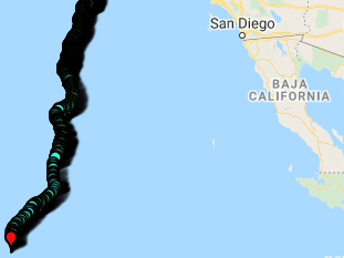
Either way, its going into an inflatable pool for testing battery performance in my backyard tomorrow, and will hopefully go for its first true navigable tests in Lake Merced next week.
Nose and rear cone fabrication will need to wait…